Robotics, Computer Vision, Machine Learning

Category: Kuroki – Machine Learning on a Robotis Mini

Learning to walk with a Robotis Mini

In this post I will develop the following main components for the Robotis Mini:

  1. A parametrized walking trajectory generator
  2. An interface to receive walking parameters and reset the Gazebo simulation
  3. A program that explores the space of walking parameters of the robot by setting them and observing the “quality” of the simulated execution

The parametrization of the walking trajectory generator and parts of the code are based on the one existing for the big brother of the Robotis Mini robot, the Darwin robot. In this link you can learn more about it. The idea is to create the walking trajectory as a set of sinusoids. This defines the parameter space of the trajectory as the parameters that define these sinusoids. Based on the aforementioned code I defined a walking trajectory generator and expose its parameters to be assigned with ROS calls.

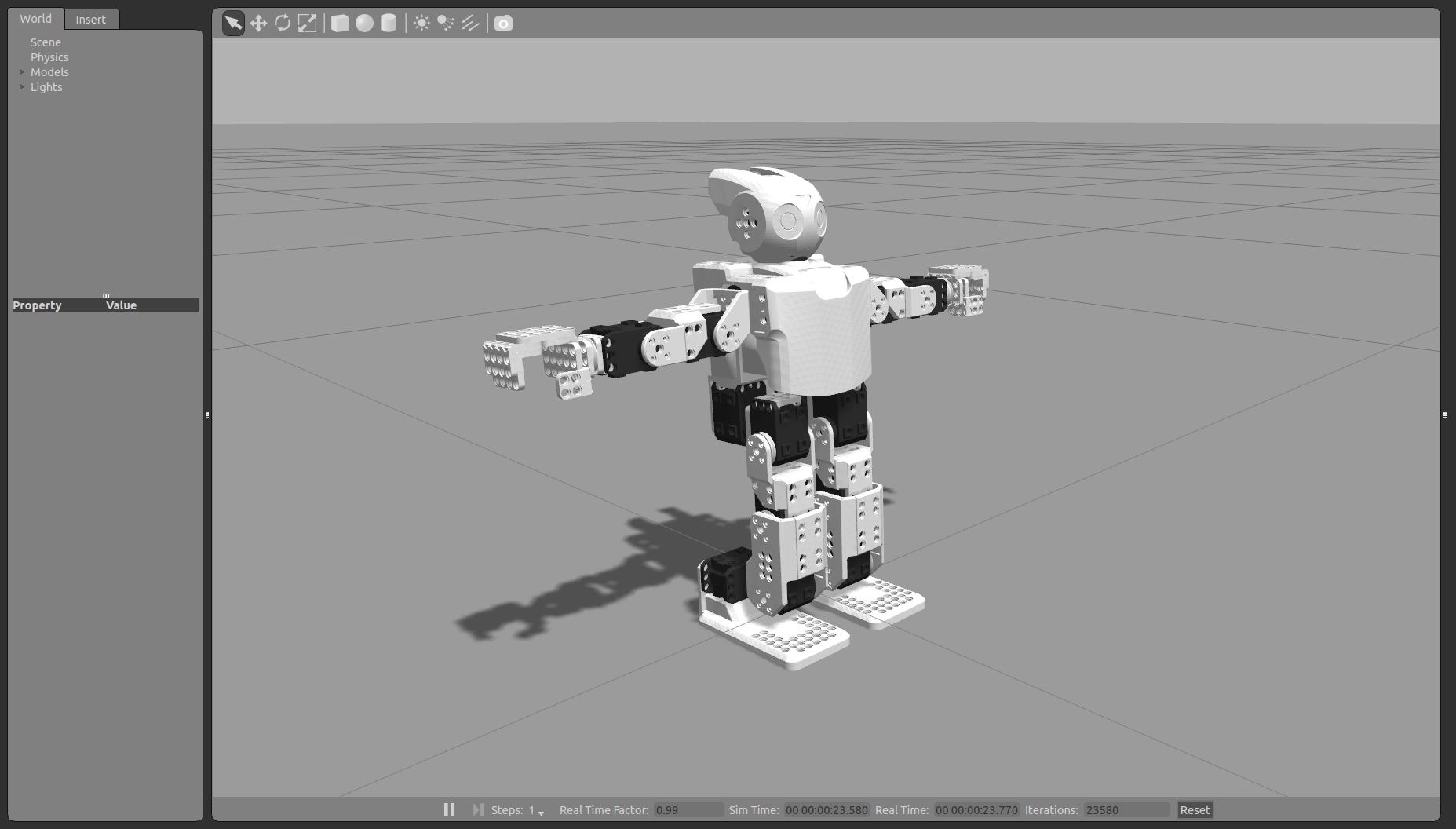
Then, I created a program that sends walking parameters and observes the height and distance traveled by the robot’s head during execution. These values are the reward associated to the walking parameters. In a first step I just grid searched for an acceptable set of parameters that make the robot to move without falling. I found a good set of parameters which I defined to be the default ones at the beginning of the execution.

Finally, to close the loop, I tested this first set of parameters found in simulation on the real robot. The idea is to be able to switch seamlessly between simulation and real robot. The execution of this first set of parameters, while not very graceful, really matches the simulation! Remember that this set of parameters is just the best scoring of a grid search, I did not implemented yet any real learning method to improve the search.

In the next post I will report on the steps to implement a real machine learning approach to learn the optimal set of walking parameters. The technique that I will be using is black box optimization (instead of reinforcement learning) because:

  1. It is easy to implement
  2. Requires a single scalar value as reward for an entire rollout (execution of a trajectory)
  3. Explores in the parameter space of the actions, not in the outcome of the policy
  4. The exploration of new parameters is performed with noise on the parameters that is constant (wrt time) along the entire trajectory

Simulating Robotis Mini in Gazebo

In this post I will extend the URDF model I created in the previous post to be used to simulate a Robotis Mini robot in Gazebo ROS. I will include dynamic and other properties that are necessary for the simulation.

First, I will add collision bodies to each of the links of the URDF model. Gazebo uses the collision bodies to compute contact points / collisions between surfaces. The URDF format has two ways of defining collision bodies: as a set of geometric primitives (cubes, spheres, cylinders) or as a mesh model in stl or collada format. My first idea was to use directly the same mesh files I used for visualization (the ones provided by Robotis). However, the complexity of the computation of collisions grows with the level of detail of the collision body models (i.e. the number of triangles of the mesh model if it is not a geometric primitive). And the mesh models for visualization contain a lot of details! Using these highly detailed mesh models would slow down the simulation. Additionally, many of these details, like the holes, are useless for the collision computation.

Therefore, I used MeshLab to create a second mesh file for each robot part containing a lower resolution mesh model. Meshlab provides both a convex hull computation (for convex shapes) and the filter “Quadric Edge Collapse Decimation” that are very useful to reduce the complexity of a mesh model. I saved the simplified meshes with the same name and the suffix “_s”.

Next, I added some dynamic properties to the URDF model. To the robot links I added friction and inertial properties (mass and inertial matrix). To the robot joints I added transmissions, joint limits and maximum effort and velocity.

Then, I added the gazebo_ros_control plugin to the URDF model and defined a set of ROS controllers for the joints of the simulated robot. These controllers are loaded through a ROS controller manager node. I defined the controllers in a yaml file in the “config” folder inside the robotis_mini_control package.


Gazebo simulation of the Robotis Mini robot

Gazebo simulation of the Robotis Mini robot

Finally, I created a new package called robotis_mini_gazebo inside the robotis_mini_ros meta-package. This package contains a Gazebo world model and launch files to load Gazebo, the URDF model and the joint controllers. The world model is currently almost empty: it just defines a new initial viewing pose closer to the robot. I can now launch the execution of a simulation with my Robotis Mini model with the command:

roslaunch robotis_mini_gazebo gazebo_and_control.launch

Well, the simulation is up and running, I just need something to simulate! That means, I need a method that sends commands to the simulated robot, records the outcome of the execution (reward, cost) of these commands and learns the best set of parameters to achieve a task. It is getting interesting!

Creating a bridge between Robotis Mini and ROS

In the last post I explained how to interface the Robotis Mini robot with python using the pypot library and a Robotis Mini module I created. In this post I will make use of this functionalities to connect the robot to the ROS environment. My goals are:

  1. read motor states and publish them to ROS as JointState messages
  2. get motor commands from ROS (controllers) and send them to the robot
  3. visualize the robot on RViz

Therefore, in this post I will explain how I created a ROS node that will take care of 1) and 2). This node will have to create a RobotisMiniPoppy object (pypot library) and use it to read/write to the robot, and create and use the corresponding publishers/subscribers to ROS.

Then, I created a URDF model of the robot. I found some existing URDF models for the Robotis Mini that I could use to start with and extend. The URDF will use the CAD models provided by Robotis for each robot part.

Finally, I created two launch files:

  • one to connect to the real Robotis Mini robot and visualize it in RViz
  • a second one to visualize in RViz a virtual Robotis Mini. Its joints can be manually set using the joint_state_publisher node GUI.

I created a meta-package robotis_mini_ros that contains two packages: robotis_mini_control (for all the control related stuff for the robot, also for the bridge node to connect to the real robot) and robotis_mini_description (for the URDF and the launch files). It is publicly available in this repository: https://github.com/roberto-martinmartin/robotis_mini/ This github repo also “contains” the pypot module I created for the RobotisMiniPoppy pypot code as a submodule (a submodule in a git repository is like a link to another repository; it allows you to match and pack together versions of both repositories).

RViz visualization of the Robotis Mini Robot

RViz visualization of the Robotis Mini URDF model

To launch RViz and the bridge to the real robot I just execute:

roslaunch robotis_mini_descriptor real_display.launch

To launch RViz and visualize a virtual robot I execute:

roslaunch robotis_mini_descriptor mockup_display.launch

To recap, now it is possible to:

  • connect to the real robot, send commands and query the state of the motors
  • connect the robot to the ROS environment
  • use the robot URDF model that defines the kinematics of the robot in combination with the motor values (joint values) to estimate the pose of each link of the robot
  • visualize the real or a virtual Robotis Mini robot in RViz

So what is next? The goal I am pursuing by connecting the robot to ROS and defining a model of the robot is to be able to simulate the robot in Gazebo (ROS physics simulator) so that I can use this simulator to generate and collect data necessary for any machine learning algorithm. The idea is that if I can simulate the robot in Gazebo, I can easily switch to the real robot whenever I want to test the results of the learning process on the real Robotis Mini, but I can leverage the simulator to generate large amounts of data. In the next post I will then develop the necessary models to simulate the robot in Gazebo.

Using the PC as motor controller through USB2AX and pypot

In this post I will report on my steps to connect the Robotis Mini to my PC. I will use the PC to 1) read motor state, and 2) send motor commands.

In previous posts I reported on the physical connection between the PC and the motors through the USB2AX. Now we need to develop a program that sends and receives information to/from the motors through this USB2AX. There are several libraries implementing the dynamixel protocol to read/write to motors. However, I found pypot, a python library developed by the Inria Flowers Robotics Group  in France, which directly takes care not only of the low level communication to the motors, but also provides very useful “higher level” interfaces to define robots from groups of motors. And all of it in python, so it is easy to use, to test (using for example a ipython console) and to program with.

First, I was playing around and getting familiar with the library and its possibilities. Then, I created a python module that defines the motor structure of the Robotis Mini and makes it available to the pypot library as a new robot creature. This module can be found here: https://github.com/roberto-martinmartin/robotis_mini_poppy/ . The module is very simple and has two main goals:

  1. define the RobotisMiniPoppy class deriving from AbstractPoppyCreature class, which makes it to inherit all the basic functionalities of the base class to read, write and control motors
  2. provide a json file with the configuration of the robot (motors, their IDs and configuration)

Because when I connect the USB2AX to my PC it always gets the /dev/ttyACM0 port, I hardcoded it in the json file. However, it could be that in another computer the assigned port is different.

After I installed this module, I could use pypot with my Robotis Mini robot! I was playing around with the pypot + my RobotisMiniPoppy class in ipython. I was able to:

  • read and wrote motor values
  • activate, deactivate and change the color of the LEDs of the motors
  • record a robot trajectory executed kinestetic teaching (manually moving the robot motors) and replay it afterwards

My next step will be to add another level of abstraction and ROSify the robot. I will use pypot to create a bridge between ROS and the Robotis Mini robot. This will allow me to use ROS packages to control, visualize, record trajectories in rosbags, …

Change of strategy

I gave up on using the OpenCM board and decided on a change of strategy. The reasons for this change are:

  1. The specific board I have seems to be faulty
  2. The board is just a microcontroller that can execute only very simple scripts. Thus, the “real” computation would require a PC anyway.

If I am not going to use the OpenCM board to control the robot, what options do I have? There are mainly two practical ways I could get to my goal of developing robot skills using machine learning on the robot. The first one is to equip the robot with a more powerful board, something like an Arduino or a Beaggle board. The benefit of this approach would be that everything is mounted on the robot, which makes it self-contained (sensing-acting-learning). The drawback is that programming these boards, while not very different to programming in a normal computer, presents some limitations (specially the Arduino that is a controller and not a “full” computer). Practically, it would be also a big change in the embodiment of the robot to mount a board like the ones commented.

The second option is to use my computer as “brain” for the robot. This requires connecting all sensors and motors to the computer. The benefit: I can program on my computer as I usually do. The drawbacks: it is not that nice (not all self contained on the robot) and I need several cables connecting the computer to the robot.

I decided to follow this last option. And given that I have to order some hardware I decided to also remove the batteries and power the robot directly from a AC/DC converter. I ordered:

  • a USB2AX dongle (https://www.generationrobots.com/de/401584-usb2ax-fur-dynamixel-servomotors.html)
    • This will be used to read/write to the motors of the robot
    • This dongle was developed to be connected and control a chain of dynamixel AX motors, but it can be used also in a chain of dynamixel XL 320 motors (the ones on the Robotis Mini) just by using the right cable connector (the cables are similar with a +V, -V and Data channels)
  • a 6 Port AX/MX Power Hub (https://www.generationrobots.com/de/402302-power-hub-6-ports-ax-mx.html?search_query=6+Port+A
    • This will be used to 1) connect an AC/DC converter that will provide power to the motor chain, and 2) as hub to connect several motor chains to the USB2AX
  • 3P 190 mm Cables for XL Servos and cables 3 pins 100 mm for Bioloid and Dynamixel
    • I will modify the cables to have AX connection-XL connection so that I can connect the motor chains of the robot (XL) to the power hub (AX). From the hub to the USB2AX I will connect using a normal AX-AX cable
  • A regulable AC/DC converter for 7 VDC

In the next post I will explain the steps to 1) connect the robot to the computer directly, and 2) power the robot with the AC/DC power (no need of batteries!)

Downloading sketches to the OpenCM board

It was not easy but I can finally compile and download sketches to the board! To do that I use a modified version of this python script https://github.com/tician/opencm-1.5/blob/master/hardware/tools/opencm.py. The reason I can’t download sketches using the openCM IDE is that the replies from the board during the download process are corrupted. For each command sent by the PC over the USB the board replies with a corresponding response. For example, at the beginning of the download of a new sketch the PC sends “AT” and expects to receive “OK”. However, using the python script and some tests on ipython I figured out that the board is not responding correctly. For “AT” is replies “-\nOK\r\n-“, with randomly missing characters. What is the reason? Some guys from the trossen forum guess that it is a faulty bootloader on the board. The bootloader is like the operating system of the board, and it seems that it cannot be written with the PC over the USB (needs to write on special memory region) but with an special hardware. I am not sure, it could also be some problem of the USB connection.

Anyway, I can now compile sketches using the OpenCM IDE and send the generated .bin file using the modified python (I will upload it soon to github).

Next, write a sketch to read commands from the PC and send the state of the motors back.

First program on the OpenCM board

Once I could connect my USB to the mini USB of the OpenCM board I wanted to try my first program on the Arduino-like board. I installed the OpenCM library for Linux and took one of the included examples, compiled it and tried to download it to the board (download means copying from the PC to the board). ERROR! The download failed. Good start!

I searched for information and I found that you can force the download by pressing a tiny button on the controller when connecting the USB to the PC. I did so, a LED stayed green as it should, I tried to download and… ERROR again!

Then I decided to just check the other functions to see if the “rest” was working. I connected with the app and tried to move the robot, but it was not reacting. So now I have a 300€ brick, great…

No other solution that to switch to windows. On windows I expect to have more luck because I can use 3 pieces of software from Robotis that are not available for Linux: R+ Motion, R+ Task (to program motions and sequence of motions, called tasks) and RPlus. First, I tried to download a program using the OpenCM library on windows. Again, error. Then I tried to connect R+ motion or task to the robot: again error. It seems to be a problem of the USB communication.

Ok, let’s clean the mess. Next step: reset the board to its initial state using RPlus. But to reset the board I need to connect with the USB, and this seems to not work… Finally, I could reset the board using RPlus by using a different USB port on my computer. I repeated and tested different configurations, to be sure: it looks like only one USB works, and not always.

Finally, and just to be sure I still have the cool demo moves, I reinstalled the original motions that come with the robot. When resetting the board they had got deleted. I downloaded the motion file and wanted to send it with R+ motion, but the connection was impossible. I need to connect over the bluetooth.

The bluetooth connection was not working because I needed to change the settings of the bluetooth service so that new devices could be added. Once I figure out that, adding the device and connecting to it was easy. Then, loading the old moves was also easy. Now, everything is like at the beginning.

From now on, I know what to do if I program the OpenCM board and I want to go back to the initial state: go to windows, plug the board to the first USB (closest to the screen) while pressing the button on the board, reset to initial state using RPlus, connect via bluetooth with R+ motion and load the old motion file.

Next time, first steps on an on-board program to read commands from the USB, send them to the motors and output motor information over the USB.

First steps

The first thing I did was to play around with the Android app. Yes, I know it’s lame to play like a kid at my age but it was a lot of fun watching the robot dancing and falling down so many times…

The next thing was to sit down and think if the current hardware (the “CPU”) is enough for what I want to do, even if I don’t have yet a very clear idea of what I want to do. The options are:

  1. Replace the OpenCM controller by something more powerful and generic. Here the best options are:
    1. Arduino
    2. BeagleBone (I have some experience because we use it in my lab to control the air flow to the soft hands we build)
    3. Raspberry PI
  2. Keep working with the OpenCM, even if it is so limited in terms of computational power and memory space.

While digging into the code examples for the OpenCM I found a piece of code that allows to send commands and receive feedback from the USB connector of the board. Voilá! I made a decision! I will keep for now the OpenCM, program it to receive commands and send feedback over the USB and use my computer to carry the heavy load. In this way I could even mount on the robot a “real” camera (the color sensor that is available for the robot is rather a joke) and connect it to my computer, too. Another reason to keep the OpenCM is that the other options would imply to get to know how to program and control the motors using a different board, which is not what I want to focus on.

Once I decided on this, my next step was to connect with the OpenCM board using a mini USB. To do that I needed to cut a hole on the front part of the robot torso because the mini USB connector is hidden there.

In the next post I will report on the first steps programming Kuroki.